Background
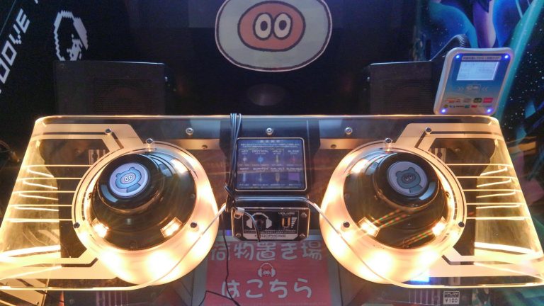
My friend Michael is a big fan of the arcade version of Groove Coaster. Whenever we go to the local Round 1, we spend a goodly amount of time in front of that machine. However, we don’t make it there more than maybe once a month, at best, and that just won’t do. Let’s bring it home!
Home Versions
We had researched previously what it would take to bring the arcade experience home. As far as the software goes, there is the Steam version and the Nintendo Switch version. There’s also running the arcade version from your PC, but then you’re also beholden to running it in a vertical monitor setup, and that doesn’t jive with my game room projector setup.
Having done some research on Steam vs Switch versions, it sounds like the Switch version is preferrable. However, a large part of the draw of this game is the funky controller.
Controller
Without the arcade controller, the game is still fun, but not nearly as fun as the arcade experience. There is a 3rd party controller, but both its availability and price are off-putting, especially since the game is best experienced in two-player mode. I’m not paying $500+ for Michael and I to play this at home.
I then looked into DIY solutions, of which there are a few. This one on instructables is basically the only documented one, and it is cool, but not exactly arcade-accurate. I also found this one on thingiverse, which is fully printable, but also not dimensionally arcade-accurate. Then I found github.com/vikbez/groovecoastercontroller, which looks to be arcade-accurate, and thus what I’m now trying to build from.
Issues
I have a 3d printer at home, but no laser cutting setup, so the main issue for me to manufacture this thing is making the box. I could maybe 3d print the box, but not as-is, as the width of the box is wider than my print area. I have no modeling skills at all, so I was hoping to use the design files as-is. However, when I started looking laser cutting services, such as Ponoko, I was finding that none of them offered 5mm material thickness, which is the a requirement of vikbez’s version.
DXF format
At the root, the problem with the AutoCAD DXF files in vikbez’s repository is that they are an output file, based on some model that isn’t committed to the repo. The CAD that I do know is PCB layout/EDA with KiCad, and DXF is equivalent to Gerber files. These files are functional, if you want to make exactly what the original author made, but they do not lend themselves to easy editing, if you need to customize or make future enhancements. Another example would be uploading a binary to hello world instead of the source code. This makes them free as in beer, but not free as in speech. Perhaps this was the intent of vikbez, but not really something that should be hosted on Github, in that case.
Material Thickness
DXF files are editable, but not conveniently so. Especially not by me, who had no CAD tools installed, and have never used a mechanical CAD tool in Linux before. Doing a small amount of research, I landed on LibreCAD for my attempt to rectify the 5mm material size. Looking at Ponoko, I was seeing that for wood materials, they were mostly offering 3mm and 6mm thickness. I decided to go with 6mm for my modification, as it would be stronger rather than weaker. Two frustrating hours later, I had modified all 6 DXF files to change the inner cuts to be 6mm instead of 5mm. LibreCAD is pretty frustrating to use, and there was no good way I found to multi-edit similar edges within the model. However, it seemed like something I’d only need to do once, so I wasn’t too perturbed.
Having looked at a few online laser-cutting services, I decided I was not going to go that route, as it was looking to be $100+ just for materials there. I called around a few places locally, to no avail. I then remembered that I had access to a laser cutter at PSU’s Electronics Prototyping Lab.
The great part about that, is that the material costs are way lower. The only “downside” is that you have to do the work yourself. I don’t really consider this a downside, except that the EPL is about 30 minutes from my house, and currently only open during my work hours. After looking at their material thicknesses, it became clear that neither the original 5mm thickness, nor my edited 6mm thickness would work, as the EPL’s materials are in 1/8"-1/4" inch thicknesses instead. 1/4" inch is 6.3mm, and I was curious if perhaps either sand a bit or if the material would compress slightly to make that work anyways. After all, it’s only 0.3mm. However, Ed from the EPL said that it wouldn’t compress, and the sanding would add a ton of work, and I’d still have bits of overhang that would be annoying.
I told him of my LibreCAD DXF editing journey, and he said he thought it’d take 20 minutes to do in Fusion 360. It turns out that it was more complicated than he expected, and he spent a few hours on it. In the end, we ran out of time and I couldn’t get the lasercutting done that day. Ed did a great job, but in the end I’d be back to having a model I couldn’t do any future changes to. Autodesk Fusion 360 is not open-source, and doesn’t run on Linux.
Solution
In the process of making the Fusion 360 version, Ed showed me the website MakerCase, which generates you a box model that can be easily laser cut, including all the fingers for making a good fit. The fact that this was generated from a web form had me thinking about how to do this in the general case. I had remembered a tool I had seen but never used…
OpenSCAD
OpenSCAD is a parametric modeling tool that uses code instead visual editing to design your models. I’ve actually wanted to learn it for a while, but had no real use-case. Now, the use-case had finally presented itself, so after I went home with no laser cut box, I was determined to figure out how to solve this problem once and for all.
Lasercut.scad
In first looking at OpenSCAD, I had to make sure that in the end I would get the output files I would need for the laser cutter. Unfortunately, OpenSCAD is meant as a solid modeling tool, not for 2d designs that would normally be output in the DXF format. However, I found a library that would be just the trick.
https://github.com/bmsleight/lasercut is specifically made for the exact use-case I was looking for. It not only gives new primitives for making boxes with a lasercutter, it also includes a python script to convert from OpenSCAD format to DXF format. It, in fact, supports all sorts of interesting things that I have never thought of, such as boxes for vinyl cutters and twist fittings. I don’t think I have a use for this, but I may in the future. I’m so glad this exists.
Example Surface
With OpenSCAD and Lasercut.scad in my toolset now, I was ready for action. I can give an example of why this is so good. Here’s how to define the bottom surface of the groove coaster box:
include <lasercut/lasercut.scad>;

// 1/4" inches
thickness = 0.68;

// dimensions in cm
// the (thickness*2) part is because adding finger joints
// adds "thickness" more on each side, so I'm actually working with
// inner dimensions here.
x = 20.0-(thickness*2);
y = 56.5-(thickness*2);
z = 10.0-(thickness*2);

color("Gold",0.75)
translate([0, -y/2, 0]) // this is to "center" the output to the y axis

// bottom
lasercutoutSquare(thickness=thickness, x=x, y=y,
  finger_joints=[
    [UP,    1, 2], // 2 finger joints on top / bottom
    [DOWN,  1, 2],
    [LEFT,  1, 4], // 4 finger joints on the sides
    [RIGHT, 1, 4]
  ]
);
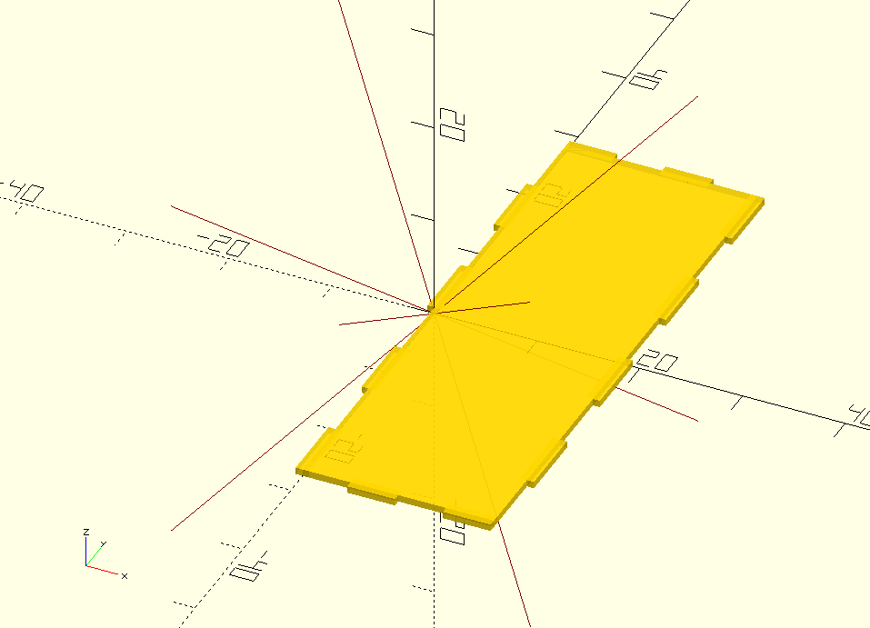
The above code generates the following model in OpenSCAD:
And after converting to DXF, looks like the following:
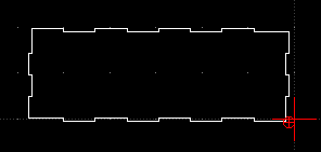
This is PERFECT. Now I just needed to generate the other 5 pieces, and I’d have a model that would work regardless of material thickness, and could also be customized to be wider, thinner, shorter, whatever, with just a few top-level variable changes.
Complication #1 - Inner Pieces
When I went through this process, some pieces were trivial to recreate, but some did become more of a challenge. The outer box in general was easy to do, but there is a middle layer within the box that the joystick and electronics mount to. There’s also a small insert piece used for mechanical strength. Neither of these lended themselves to the lasercut.scad primitives. I attemped the middle layer first, and went with using the default OpenSCAD primitive of box(), as well as some union and intersection operators. I got the right resulting model fairly quickly, but was surprised to find that when I tried to export the model to DXF, the middle layer was missing. Apparently the converter only knows how to deal with lasercut.scad primitives. Doh!
I had to figure out how to get lasercutoutSquare() to do the things I needed for it to be an inner layer, but with specific cutouts that weren’t the default finger joint type. Thankfully, lasercutoutSquare() supports cutouts, an array of rectangles to remove from the generated square. Using these, I was able to continue to use my parameterized variables and eschew hard-coding sizes into the code.
The main issue with this is that I did have some fingers, but they were basically manually added by me, since I was forgoing the built-in finger support. This meant I was dealing with the outer dimensions directly instead of inner dimensions like all the other pieces with auto-finger-joint support. That meant adding (2*thickness) to most of the measurements to make sure the generated board was the right size. This made the middle piece very verbose. Here is the code for that:
screw_offset_x = 4.1;
screw_offset_y = 2.2;
screw_r = 0.15;

insert_cut_length=2.0;

//middle
middle_side_length=(y-(thickness*2)-middle_cutout_width-(middle_slit_width*2))/2;
middle_top_length=(x+(thickness*2))/5;

translate([52, -(y+(thickness*2))/2, 0])
lasercutoutSquare(thickness=thickness, x=x+(thickness*2), y=y+(thickness*2),
    cutouts = [
        // sides
        [ // left lower
          0,
          middle_slit_width+thickness,
          thickness,
          middle_side_length+thickness
        ],
        [ // left upper
          0,
          y-(middle_slit_width+middle_side_length),
          thickness,
          middle_side_length+thickness
        ],
        [ // right lower
          x+thickness,
          middle_slit_width+thickness,
          thickness,
          middle_side_length+thickness
        ],
        [ // right upper
          x+thickness,
          y-(middle_slit_width+middle_side_length),
          thickness,
          middle_side_length+thickness
        ],

        // bottom
        [0,                                      0,middle_top_length,thickness],
        [(x+(thickness*2))-middle_top_length,    0,middle_top_length,thickness],
        [((x/2)-(middle_top_length/2))+thickness,0,middle_top_length,thickness],

        // top
        [0,                                      y+thickness,middle_top_length,thickness],
        [(x+(thickness*2))-middle_top_length,    y+thickness,middle_top_length,thickness],
        [((x/2)-(middle_top_length/2))+thickness,y+thickness,middle_top_length,thickness],

        // insert cuts
        [0,                                 ((y+thickness)/2), insert_cut_length, thickness],
        [x+(thickness*2)-insert_cut_length, ((y+thickness)/2), insert_cut_length, thickness],
    ],

    // circles_remove does what it says on the tin
    // the format is [radius, x_pos, y_pos]
    circles_remove = [
        [middle_r, thickness+(x/2), thickness+(y/2)+upper_offset],
        [screw_r,  thickness+(x/2)-screw_offset_x, thickness+(y/2)+upper_offset-screw_offset_y],
        [screw_r,  thickness+(x/2)+screw_offset_x, thickness+(y/2)+upper_offset-screw_offset_y],
        [screw_r,  thickness+(x/2)-screw_offset_x, thickness+(y/2)+upper_offset+screw_offset_y],
        [screw_r,  thickness+(x/2)+screw_offset_x, thickness+(y/2)+upper_offset+screw_offset_y],

        [middle_r, thickness+(x/2), thickness+(y/2)-upper_offset],
        [screw_r,  thickness+(x/2)-screw_offset_x, thickness+(y/2)-upper_offset-screw_offset_y],
        [screw_r,  thickness+(x/2)+screw_offset_x, thickness+(y/2)-upper_offset-screw_offset_y],
        [screw_r,  thickness+(x/2)-screw_offset_x, thickness+(y/2)-upper_offset+screw_offset_y],
        [screw_r,  thickness+(x/2)+screw_offset_x, thickness+(y/2)-upper_offset+screw_offset_y],
    ]
);
Complication #2 - Naming Things
Another issue I had was just not have the vocabulary to know what to name my variables when I was making various cutouts. I’m still not clear how to properly delineate width from length from depth, etc, as it depends on the piece and direction it is oriented. I suspect my mechanical engineer friends have this solved, but I certainly don’t. My OpenSCAD code still suffers from this problem, but I’m just dealing with it for now, until I learn the nomenclature.
Complication #3 - Duplication
I feel there’s probably way too much code and I could have been making functions or something to DRY it up a bit, but I didn’t investigate very far into that. Perhaps I will in the future.
Conclusion
All the OpenSCAD code, as it exists right now, is available at https://gitlab.com/rattboi/groovecoastercontroller/-/blob/rattboi/openscad/cad/groovecoaster.scad.
Here’s the results of that code:
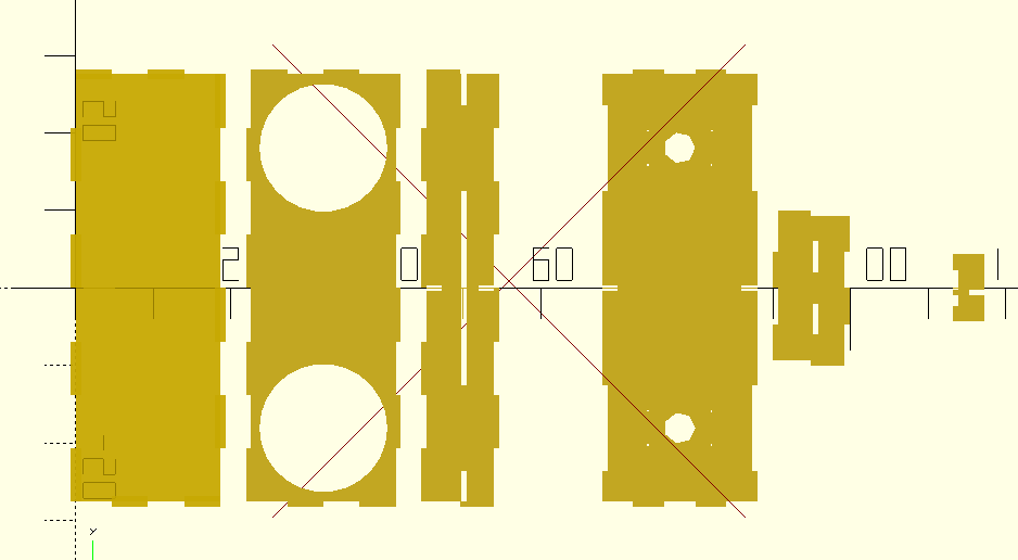
Well, this is as far as I have gotten on this project so far. I’ll be finding out if my OpenSCAD model will lasercut properly in a few days, and then I can move on to the other bits, which should be much more straightforward (I hope). Stay tuned for part 2!