Background
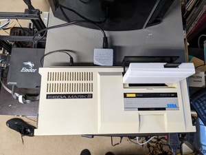
After literally years of considering, putting off, and reconsidering getting a Sega Mark III, I finally bit the bullet and snagged one at the fairly reasonable price of $160. I had been putting it off for so long because I really don’t collect console variations when they don’t grant me some sort of new functionality or capability, and I already own a Sega Master System. Two, actually… Don’t ask. However, I’ve been obsessed with how sleek the Mark III looks, and found myself checking eBay on the regular in the middle of the night. Once a good deal finally came across my screen, I was hitting that “Buy It Now” button, and as soon as I had, I knew I’d need some other accessories to make my Mark III setup legit.
Flashcart
Once the system was in my possession, of course I wanted to play games on it. On that front, I ordered a Raphnet SMS-to-Mark III adapter. I had purchased an OG Master Everdrive v1 (from Bob of RetroRGB.com, of all people) a few years ago, but never actually got around to using the thing. My simple plan was to use the Raphnet adapter along with the Master Everdrive v1 to play some sweet, sweet Sega classics.
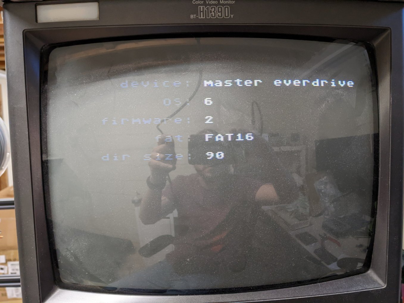
I have a few US SMS games, and was able to play some Choplifter with the Raphnet adapter to test out the Mark III. However, when I tried to use the Master Everdrive, it wouldn’t load up on the system. Unsurprisingly, I could get it to start up on the Sega Master System, but it wouldn’t show any files on the micro-SD card I had. It turns out that Bob had smuggled me some beta firmware that was apparently never released (v6), and it was old enough that the only cards that were readable by the firmware were full-sized SD cards (not SDHC), 2GB or smaller in size, in FAT16 format. Tracking down this information was not trivial, as the Internet has “moved on”, as it is known to do. I ordered a 2GB SD card on Amazon Prime and got another chance to try it out the next day. Still no loading on the Mark III… but it’d load up games on the SMS! That’s progress, in some direction at least.
Having a working SD card allowed me to update the firmware to the latest version (for the v1 Master Everdrive, anyways). This still didn’t allow me to load it up on the Mark III, despite what someone on the Internet said.
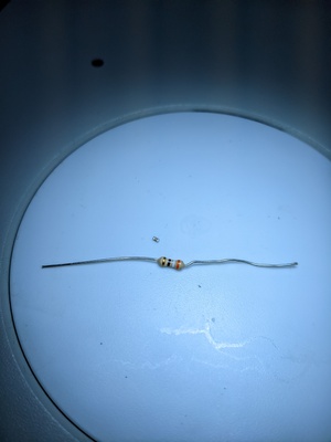
As the next attempt, there was a rumor on the Internet that there is something strange with the reset line on the Mark III compared to the SMS, and that the Everdrive actually is sensitive to the fact that the Mark III doesn’t come out of reset as fast as the Master System. The fix for this is to replace the C18 capacitor on the reset line from the original value of 10uF to 100 nF. I tried this, and in my case, it didn’t fix the problem.
Tianfeng’s Adapter
At this point, I was pretty well stuck. I actually found a Retro Core youtube video where he makes a Mark III flashcart from a Master Everdrive and an adapter, and he had also not gotten the Raphnet adapter to work, instead relying on another adapter that I couldn’t source in 2022.
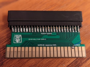
I knew Tianfeng was working on his own adapter, so I asked him about it. Graciously, he sent me a prototype that he’d already checked with the Master Everdrive v2, so I was feeling pretty good about my chances. However, when I received it, it also didn’t work! It didn’t work with my two original SMS games that worked with the Raphnet adapter, either. Stuck again…
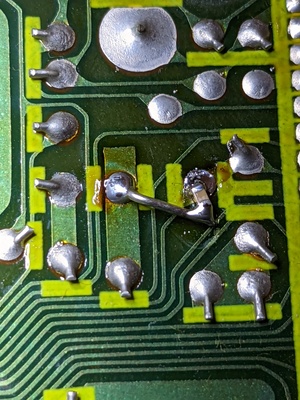
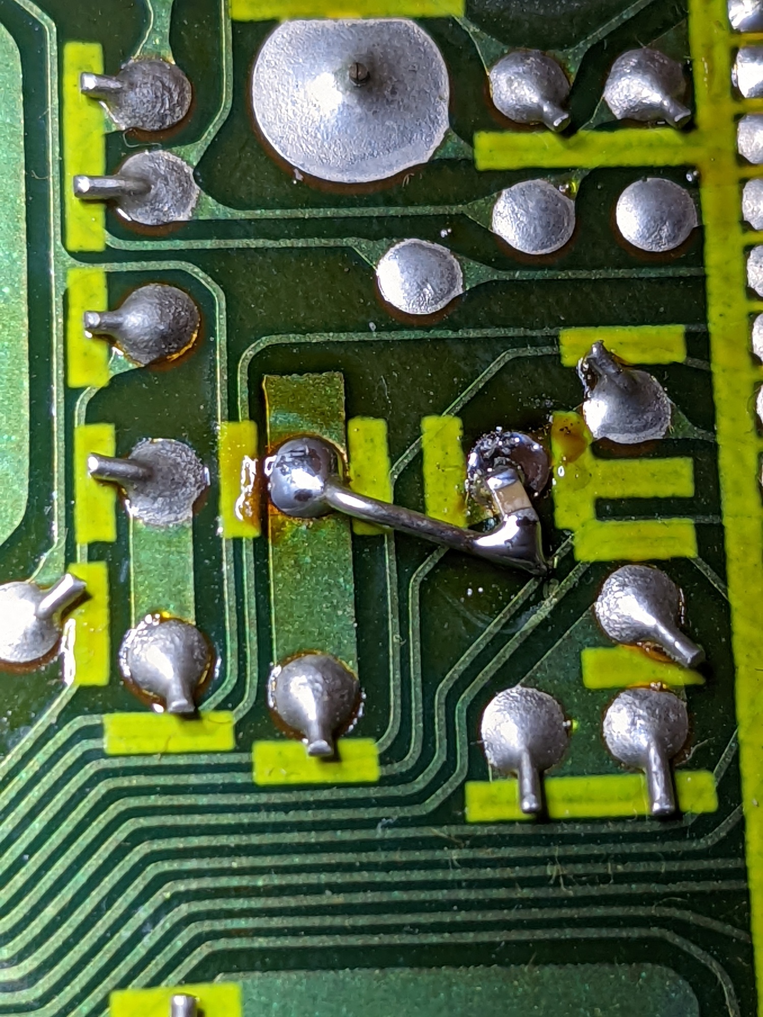
But not for long. Since I had both adapters, I decided to check them against each other. I found 2 differences between the adapters, after buzzing each out with a multimeter over the course of about 2 hours. One of the differences related to the reset line, and matched what I’d read about the Island Trade Adapter on smspower. The other difference was around how the Mark III’s A15 line was routed. On Tianfeng’s adapter, it was routed to the SMS A15 line. However, on the Raphnet adapter, it was going to SMS A15 as well as /M0-7. This makes sense, as it’s an active-low line that’s low when an address is in the range 0x0000-0x7FFF, and high if an address is >= 0x8000, which is the same behavior you get out of A15, which will be low for addresses 0x0000-0x7FFF, and high for addresses 0x8000-0xFFFF. In all likelihood, this is used as an active-low chip-select or output-enable line on the ROM in the cartridge. I took apart my copy of Gangster Town and found that it didn’t use SMS A15, but opted instead to use /M0-7. I think we found our culprit!
After a simple bodge wire…
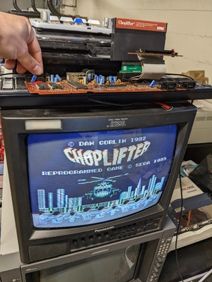
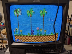
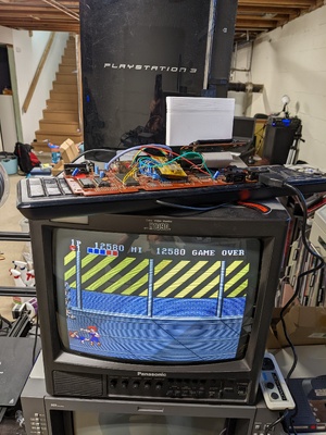
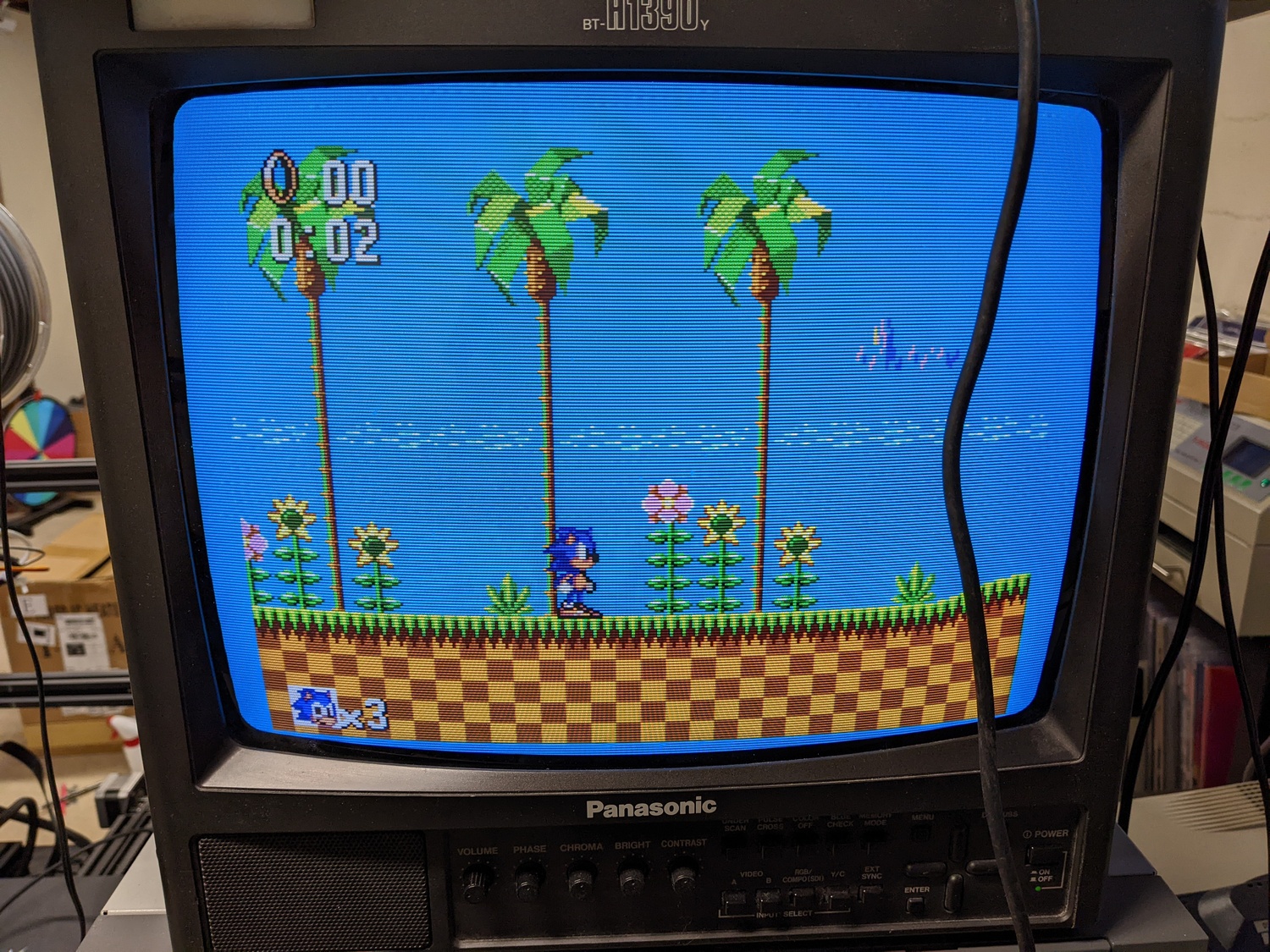
And now, the moment of truth!
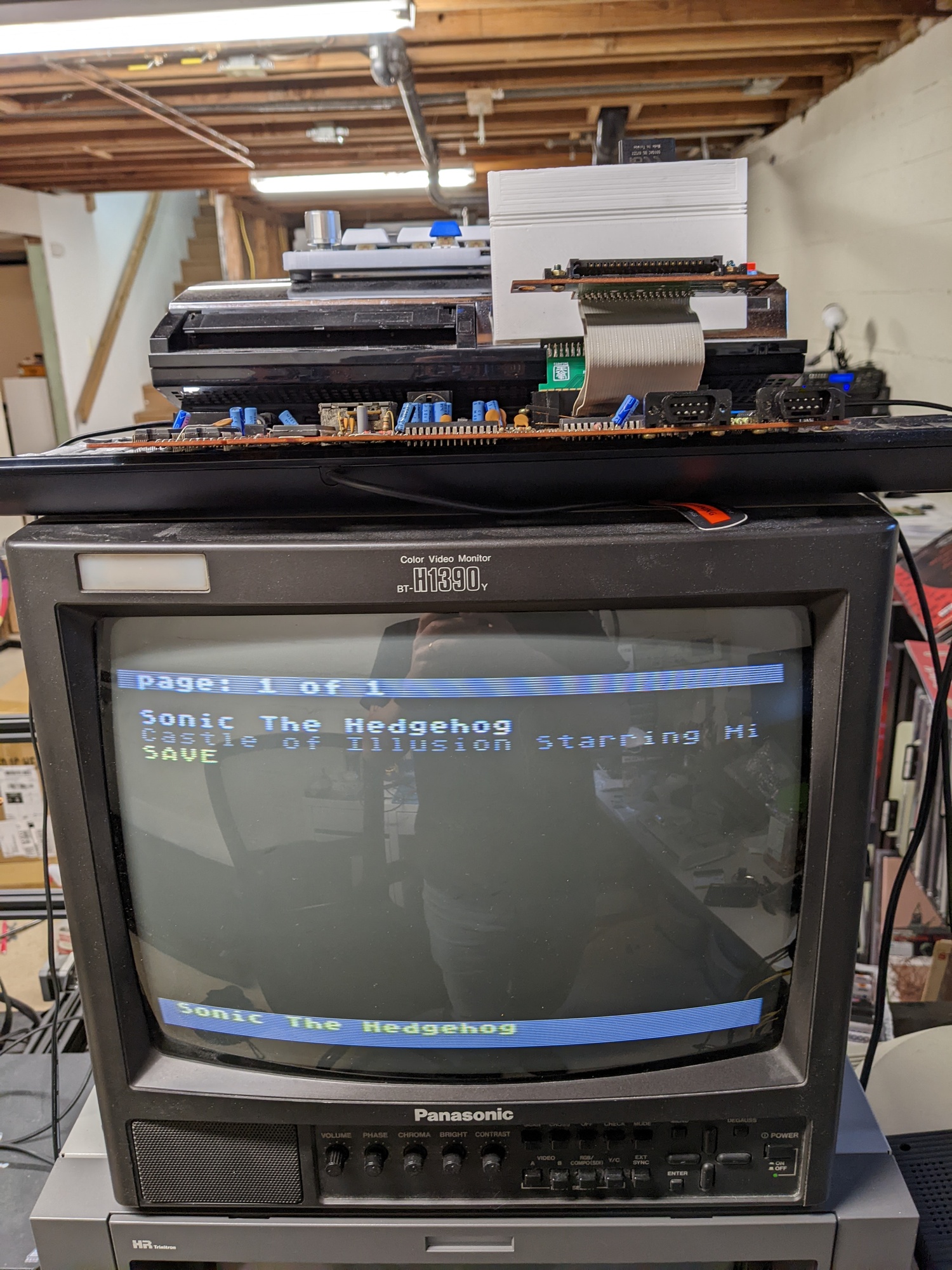
Success!
First Lessons Learned
I was so happy to have a flashcart that would now work with the Mark III. However, did we learn anything? I believe I determined why the Raphnet adapter wasn’t working with the flashcart, because of its own odd routing of the reset line. However, it’s also possible that this is correct and I’m still running into issues with the replaced reset line capacitor on C18. My fear is that we’re basically opting out of the reset line entirely and holding it constantly out of reset. This hasn’t had any ill effect on my two original games, nor the Everdrive, but that’s a really small sample size… I may go back and verify this, just by bridging a couple pins on the Raphnet adapter. Alternatively, I could try to snoop the bus on the SMS to see what the behavior of the reset line is during Master System bootup, and compare it to the Mark III. That sounds like a lot of work though…
3D Printing a Mark III Flashcart Case
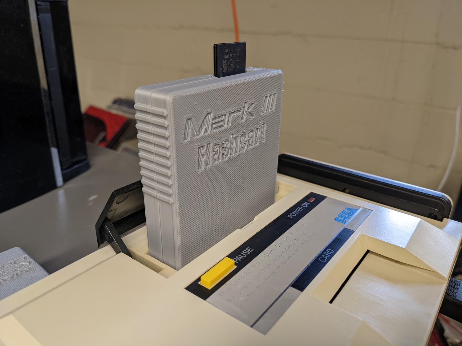
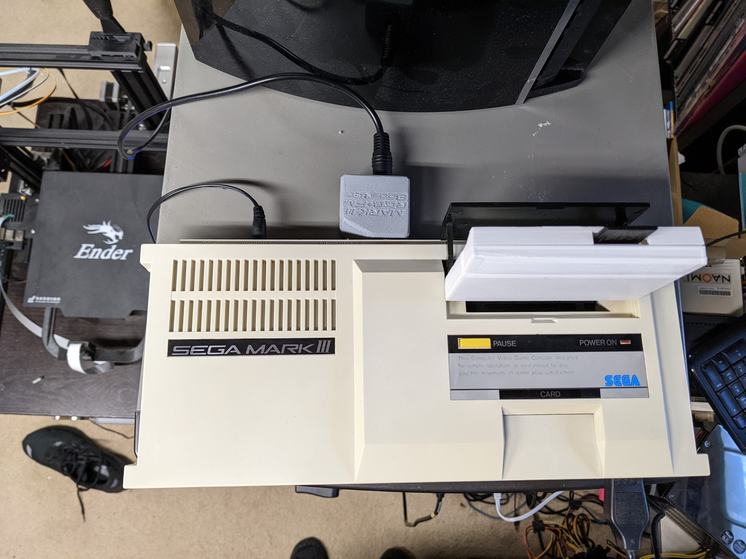
At this point, I had a fully working Mark III flashcart, but I have to admit, it looked pretty dumb floating out the top like it does in the SMS case…
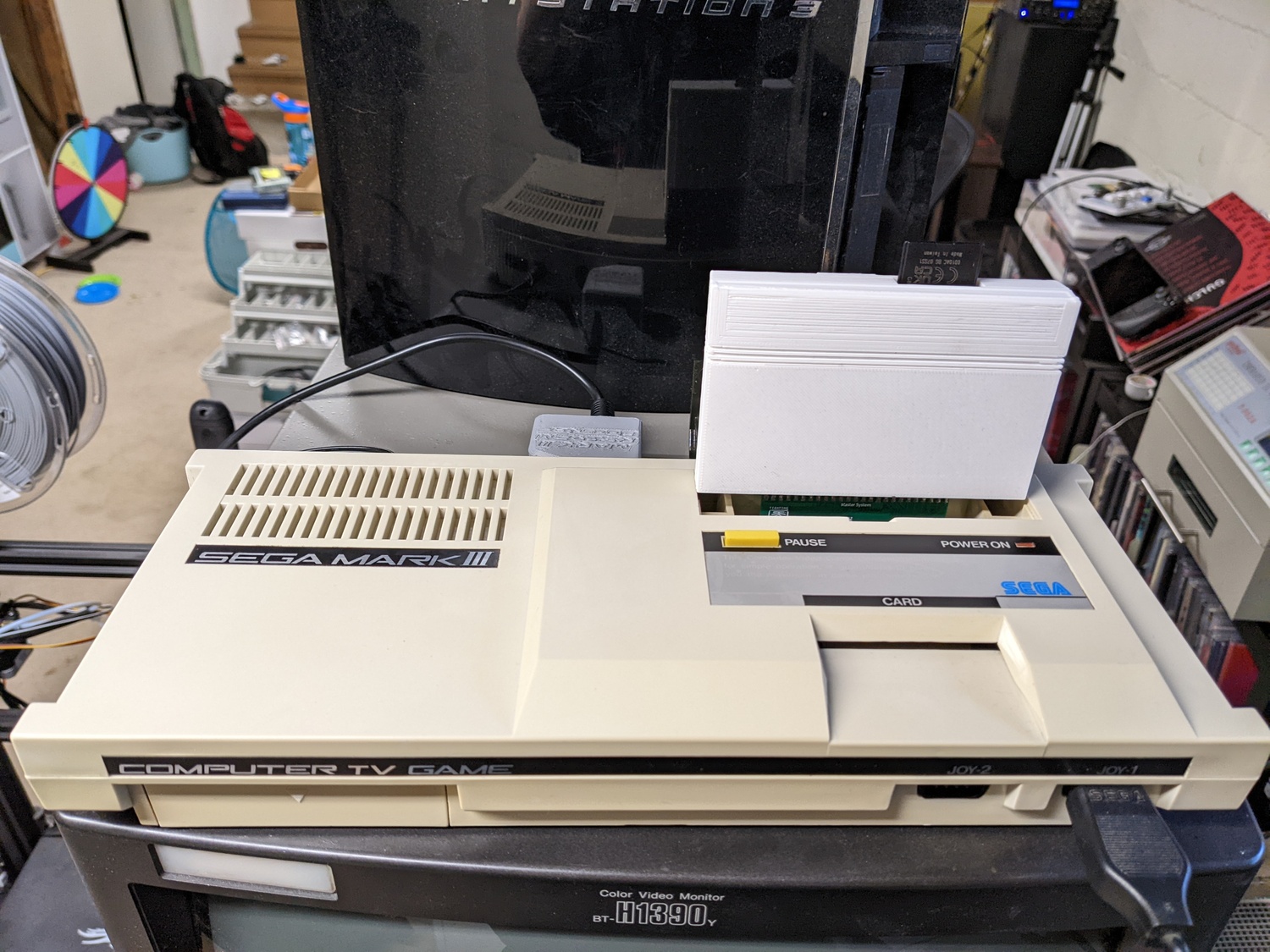
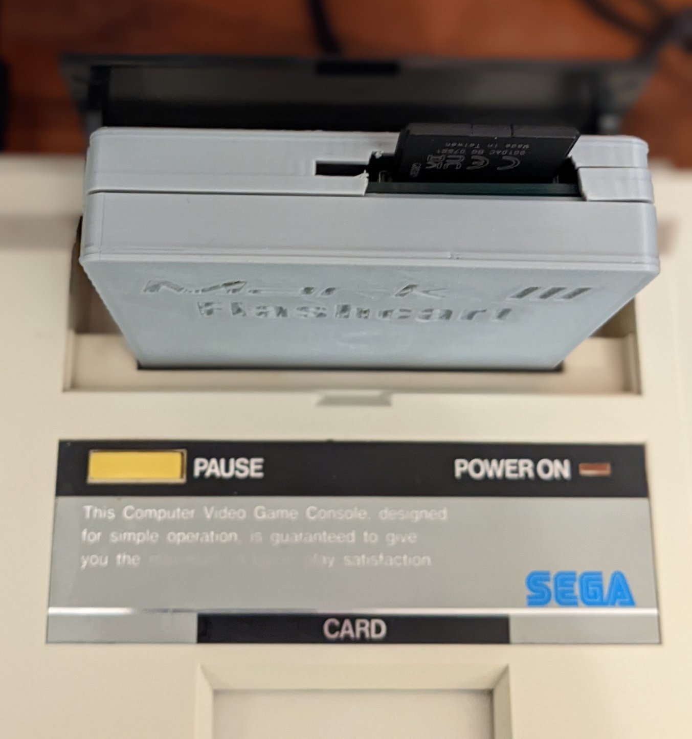
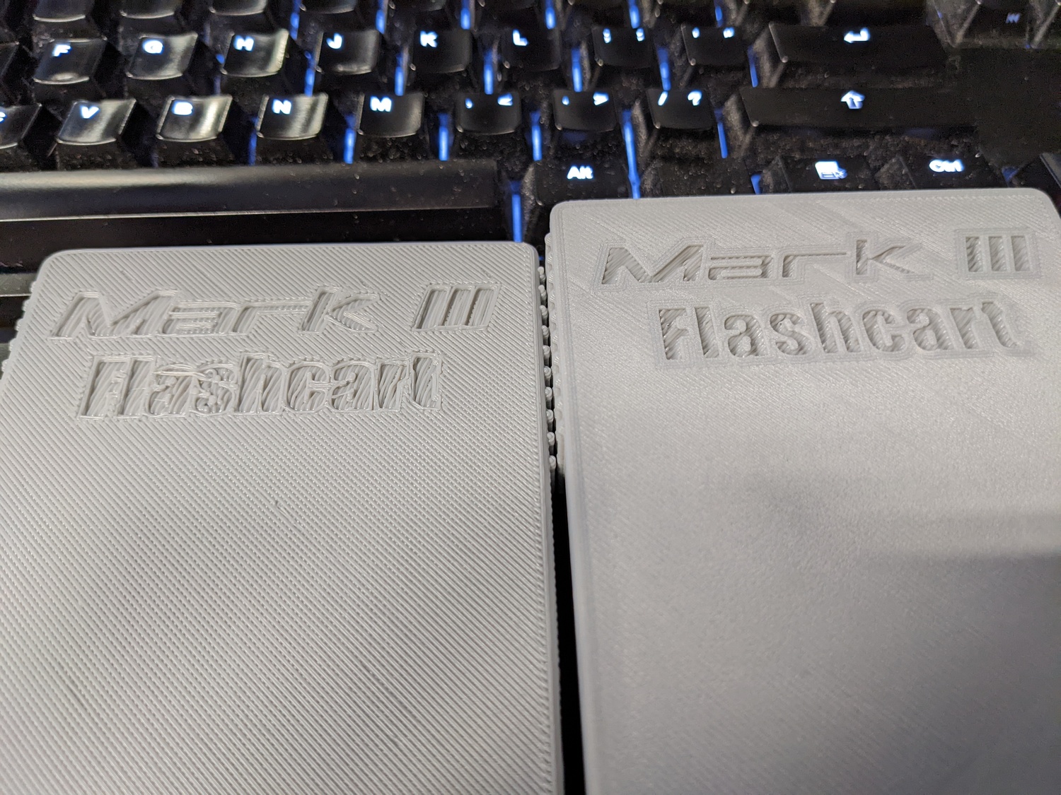
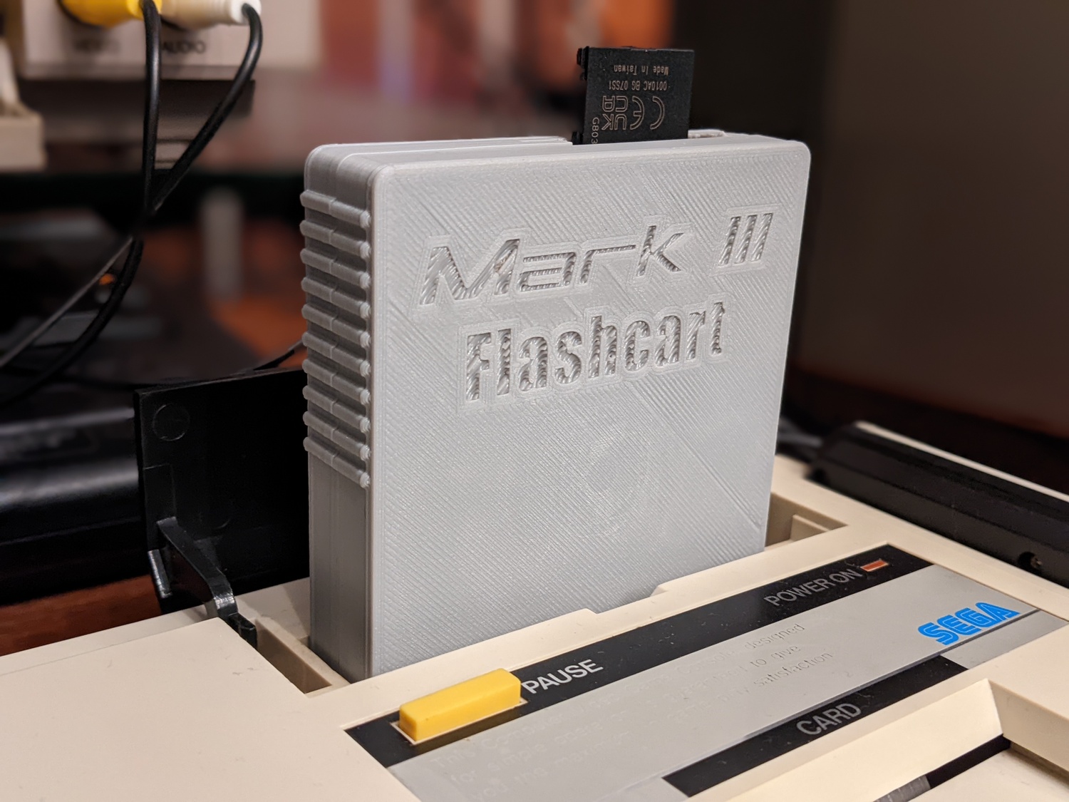
It seems Tianfeng was already on top of this problem as well. He has been working with Retro Frog to design a case that works with the Master Everdrive and his adapter, and I was granted the privilege to print my own. Having not used my 3D printer in over a year, I will say that the original print was pretty rough, so I went back and reprinted it now that I’ve tuned things up again. Either way, as a proof-of-concept, I think we can all agree it looks badass.
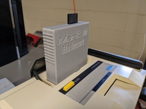


I did have to take an Xacto knife to the case, as it was designed for the Master Everdrive x7, with a centered micro-SD slot, while my v1 has a full-sized SD slot to the right side. I honestly don’t mind, as it is still fully functional and wouldn’t notice the cuts at a glance.
FM RGB Booster
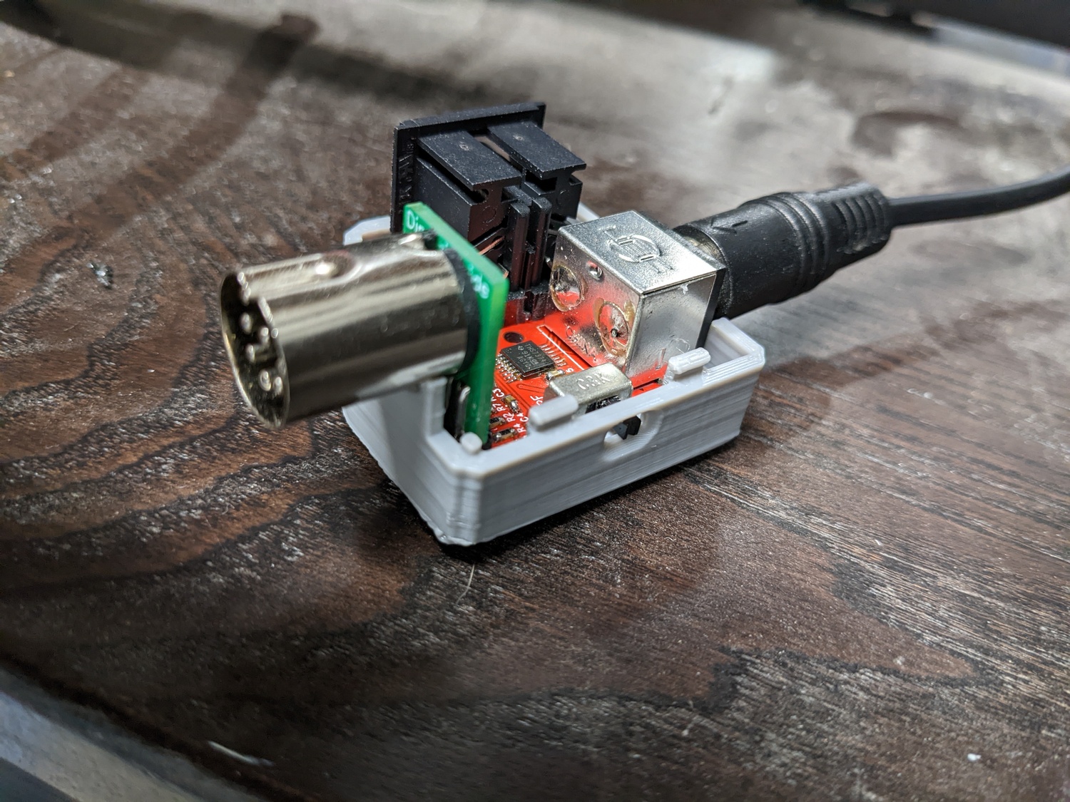
But that’s not all! Tianfeng had sent me another present along with his prototype cart adapter, in the form of an RGB booster that still allows passthrough to the FM Unit. That’s assuming you have an FM Unit, which I don’t… we’ll get there later in the post. It’s a neat board that plugs into the AV port on the back of the Mark III, allowing passthrough audio for the FM Unit, while boosting the known-to-be-weak unbuffered RGB signals, with the benefit of outputting to a Genesis 2 minidin-9 port. He also sent me the Retro Frog prototype case design, which I again had the pleasure of printing. Todd’s work is unparalleled, and I think the design is great. It looks really rough in pictures, but you can entirely chalk that up to my noob 3d printering skills. I’ll be reprinting this one as well, now that I have my printer more dialed in.

SMSFM Installation
Last thing to do was to get some excellent FM synthesis happening between my earholes, courtesy of eviltim’s SMSFM board. This was an interesting problem, as there were only small hints to previous installations of the SMSFM into a Mark III, with no documented install that I could find. First, lets spend a minute discussing why I would opt for the SMSFM over the official FM Unit. Well, for starters, the FM Unit now goes for $200+ on eBay, whereas Tim’s SMSFM is ~$75 shipped to my house. Also, I kinda don’t like how the FM Unit looks on top of the Mark III, but that’s just my personal opinion. Lastly, if I had gotten the FM Unit, I couldn’t write this exciting section about the first documented install. Those are the up-front reasons. Another reason is discovered later, so read on.
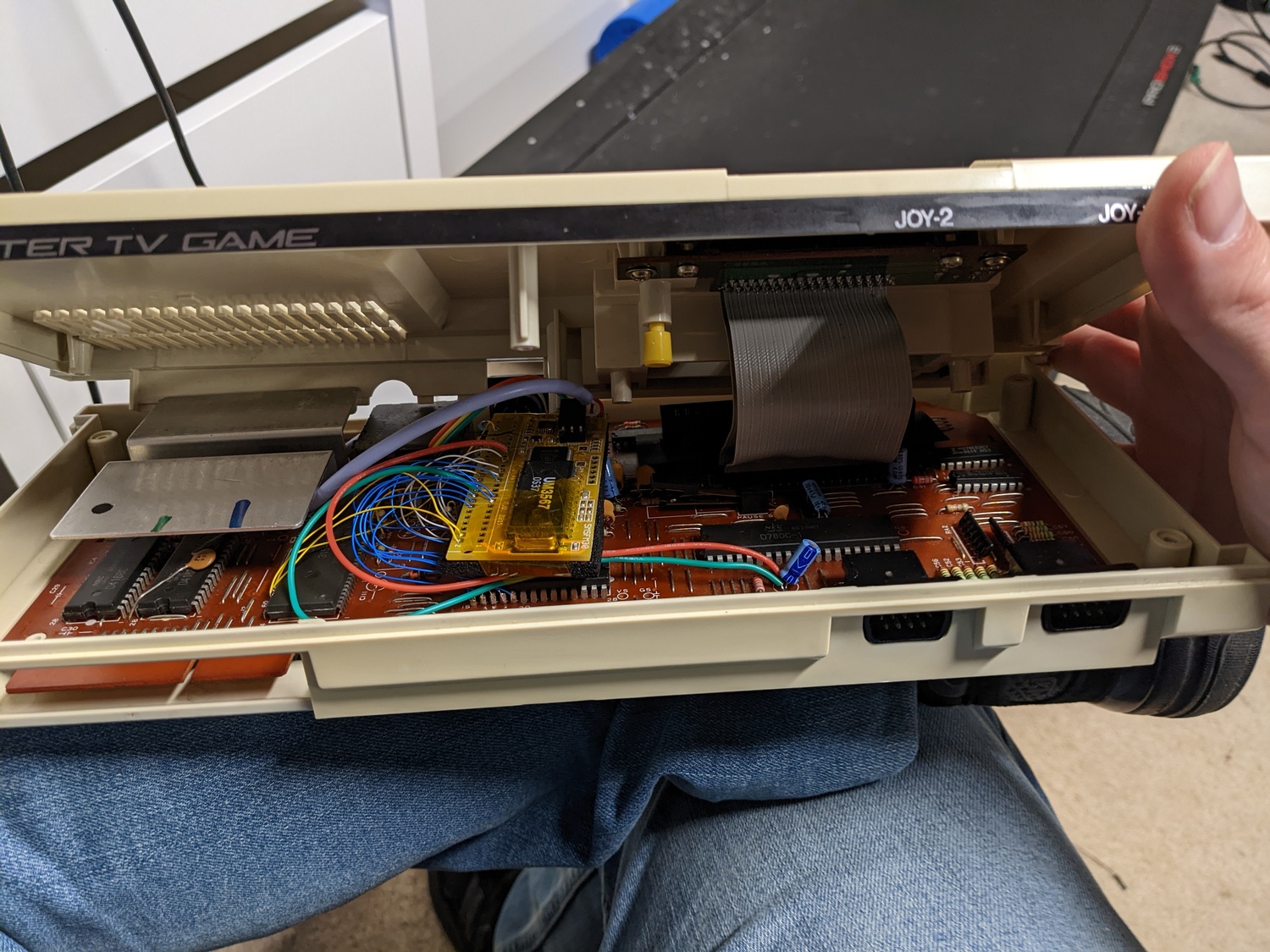
My initial idea was to see if I could just use the existing expansion port, but place the SMSFM board internally. The gist of this idea was to not need to do much of any wiring internally, but hide the board away inside to keep the sleek original lines of the Mark III. This was a non-starter after measuring how much room was available once you open the expansion door. We’re talking a couple millimeters. With that option off the table, I went for the big ol’ mess-o-wires approach. I really didn’t want to go this way, but after tracking down all the signals necessary for the install, it was clear that there was no single chip I could glom onto for the install.
The KILLG# Adventure
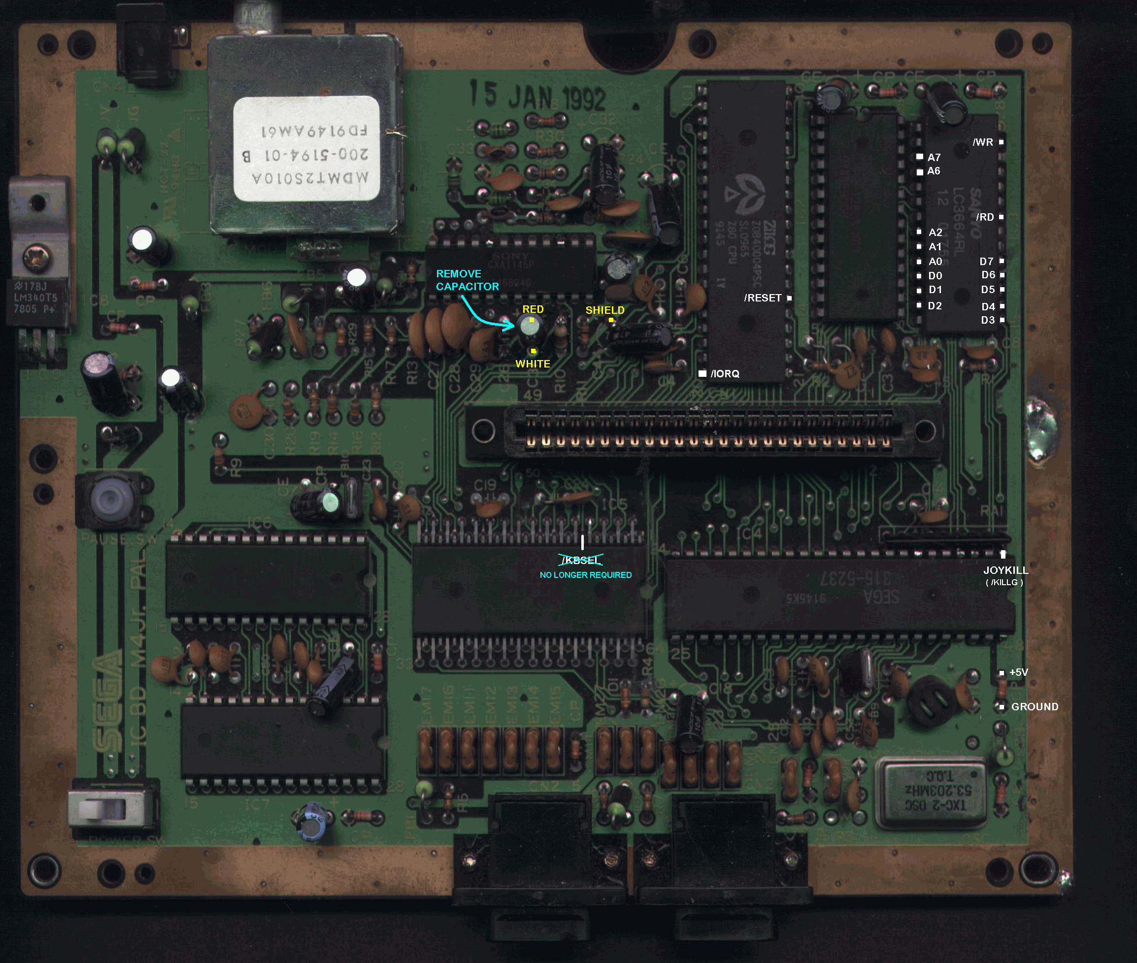
Following Tim’s instructions for how to do an internal install for the SMS2, I went to work finding the shortest groupings of connections in order to minimize the number of chips I’d be soldering to. This led to an interesting sidequest, as it wasn’t clear (to me, at least) which pin would be the KILLG# pin referenced in Tim’s documentation. I had used smspower’s pinout guide as the source of truth up to this point, and yet KILLG# isn’t listed on that site. Another conundrum was that I would assume that all signals necessary would be on the Mark III expansion port, and yet I already had a counter-case to this, in that the SMSFM wiring guide has you connect to A6, which is definitely not a signal on the expansion port. However, I still believed that almost all signals necessary would be on this bus. Random googling led me to learn two other names for the KILLG# signal, JOYKILL and JyDs. JyDs is on the smspower pinout guide, and is even described to be related to FM Unit access, but hilariously, it doesn’t show up on either the Mark III cartridge pinout nor the Mark III expansion pinout. I found a single forum post that nonchalantly says that the signal is on the expansion bus, next to the two 5V pins. For some reason, this pin is not documented on the expansion bus on smspower, showing just a white square. I wasn’t about to just take this guy’s word for it, so I took to the multimeter and started tracing it backwards. It led to IC10, a 7432, quad 2-input OR gate. After spending some time reversing this further to figure out what exactly it does, it appears to be a portion of the output enable logic for the joystick ports (and the CONT signal). The full equation is /OE = /RD | /KBSEL | JyDs. Because of active-low logic, it actually is more of an AND operation.
“The joystick outputs are enabled (
/OEis asserted), if and only if a bus read is happening (/RDis asserted), and the ‘keyboard’ is selected (/KBSELis asserted), and the magic expansion bus pin (the only signal that is active-high) is low (JyDsis de-asserted).”
/OE | /RD | /KBSEL | JyDs |
|---|---|---|---|
| 0 | 0 | 0 | 0 |
| 1 | 1 | x | x |
| 1 | x | 1 | x |
| 1 | x | x | 1 |
Remember, /OE being 0 means outputs are enabled. When nothing is attached to the expansion bus, there is a 2.2k pull-down on JyDs to ground, so we know the signal’s default value is 0.
Now that we’ve proven out that which line on the Mark III is the JyDs line, we can move on to the next step.
The Audio Mixing Adventure
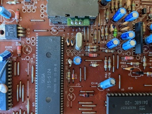
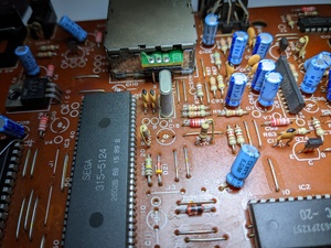
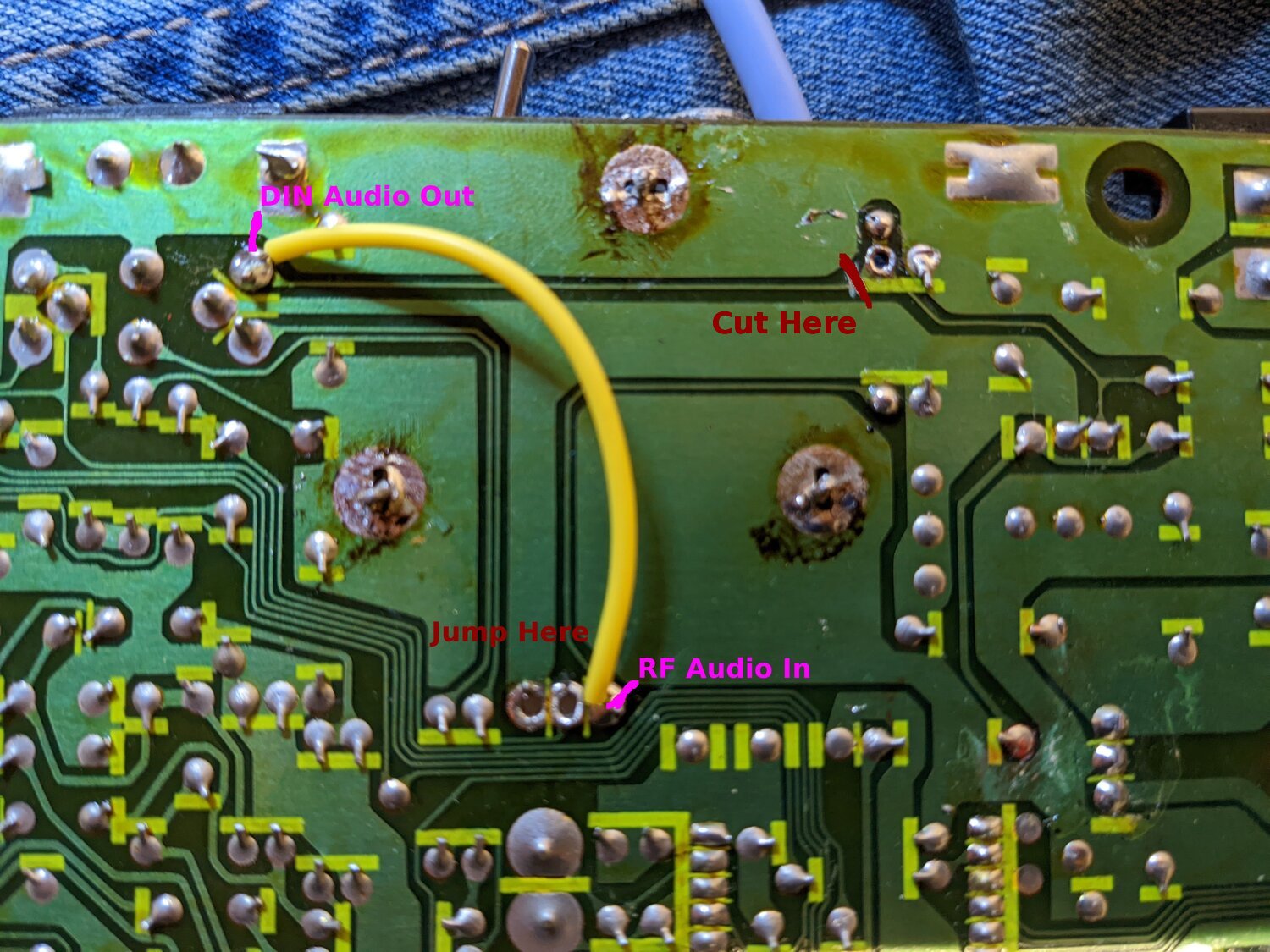
Having found the location within the Mark III of the 19 pins normally found on the SMS expansion bus, there was still the problem of how to inject the audio into the Mark III’s audio circuit. Tim’s instructions has a section on “Audio Mixing”, which vaguely says “Remove an audio cap, tap the input into the SMSFM there, and wire the output to the other side of the cap”, and then shows many examples of how to do this for various revisions of the Master System. Looking over the Mark III audio circuit, it became clear that there was no cap to remove. The audio signal leaves the VDP at pin 10, enters a simple common collector voltage follower circuit, which buffers the original signal and sources current from the PSU rather than from the VPD pin directly. The signal then goes directly to both the RF audio input, and the DIN-8 audio output. On the top side of the Mark III motherboard, there is a simple wire jumper to get the audio to the RF unit. I opted to remove the jumper, and mix the audio there. In order to do so, I had to cut a trace from that point to the DIN, forcing the signal path through the SMSFM audio input wire, outputting to the side that was only for the RF adapter. I then placed my own jumper from the RF audio input back over to the DIN, rebuilding that portion of the original circuit.
In hindsight, I think perhaps it was a mistake mixing at that point, as it is after the amplifier stage. That means more current potentially has to pass through the SMSFM’s audio mixing circuit. So far I’ve had no problems, but if I were to do it again, I’d find a way to inject before the transistor in order to better isolate the SMSFM from the outside world.
Placing the Toggle Switch
We’re really coming around the bend now. We’ve found all our digital signals necessary for the SMSFM to interact with the Mark III as an FM Unit. We’ve (somewhat) properly mixed the audio signal from the SMSFM into the Mark III’s audio path. Lastly, we need to place our switch which allows us to enable or disable the FM Unit externally. Tim’s kit comes with a 3-position switch that is wired to the SMSFM through a simple header, allowing selecting between PSG, FM (US) and FM (JP). Being the good retro citizen that I am, I wanted to find a place to position the switch that didn’t involve cutting any plastic on the Mark III’s shell. Beyond being a good citizen, I just didn’t want it to look tacky.
Looking over my options, I could have perhaps placed it somewhere through the grating, making it available on the top. That still sounds fairly tacky to me. There’s maybe somewhere on the bottom grating I could have placed it, but routing the wires and mounting it appropriately sounds like a nightmare.
Hmm… I’m never going to use the RF unit, and there’s a really good spot for a switch right there for channel 2-3 (or whatever the japanese equivalent is) selection. I wonder…
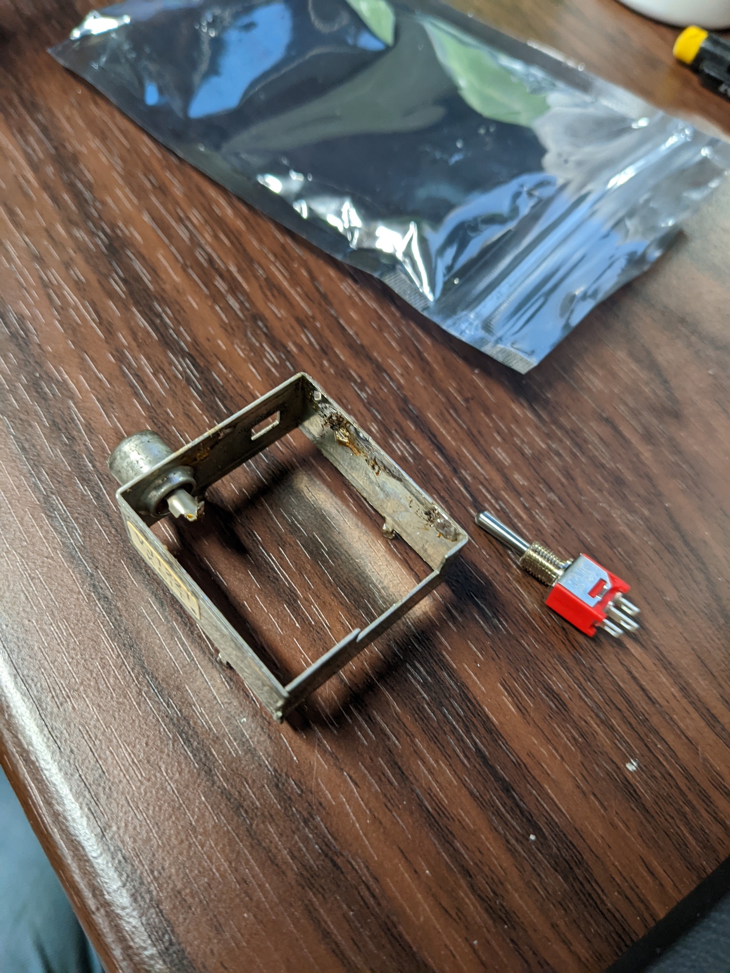
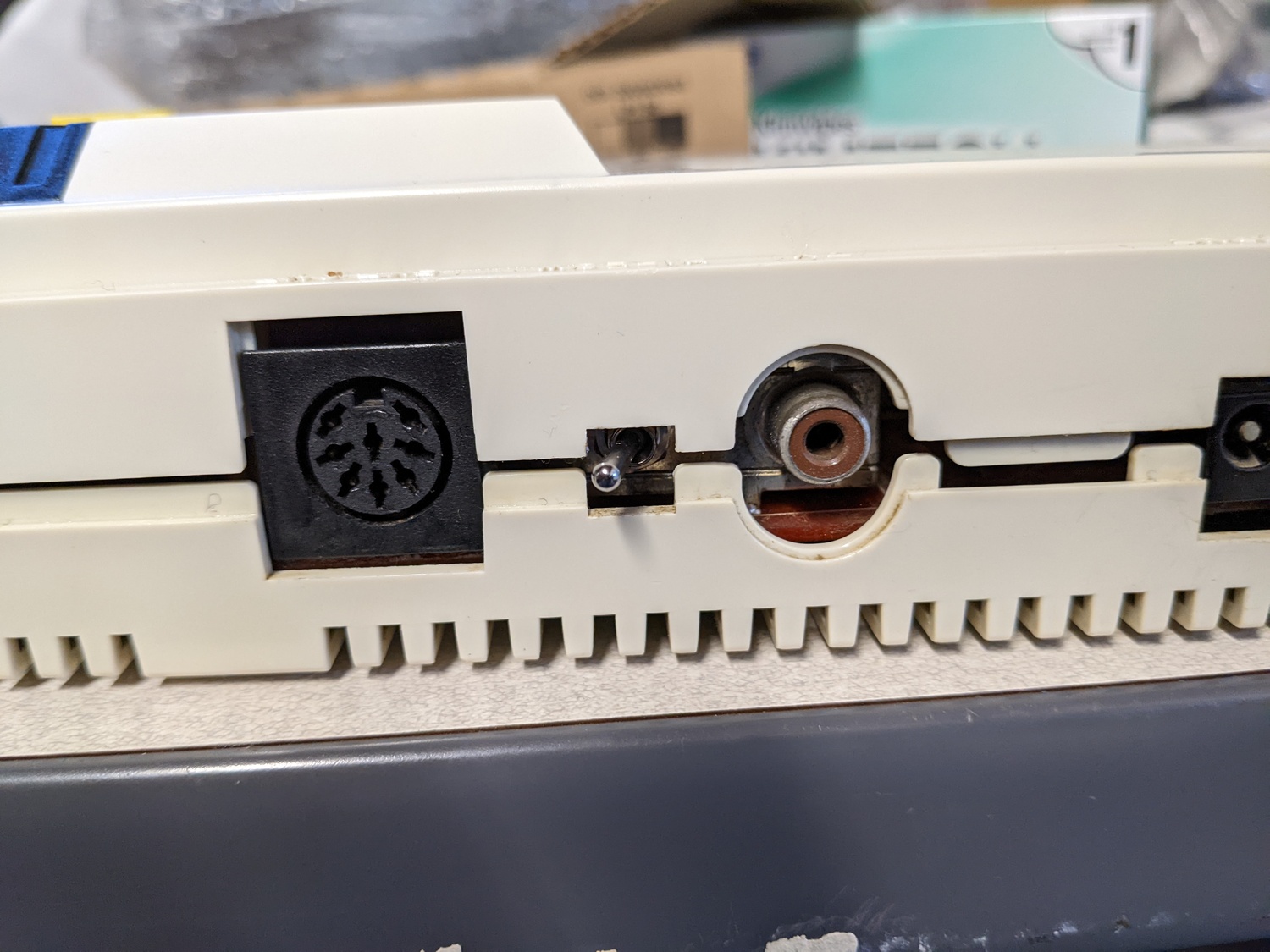
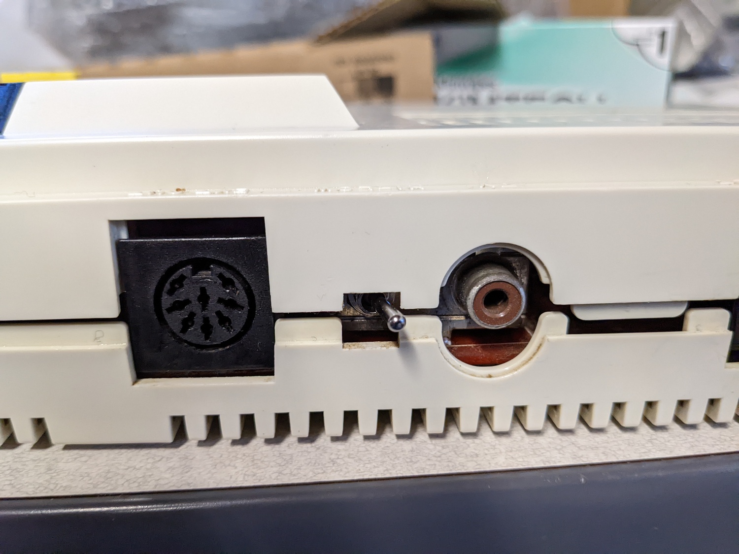
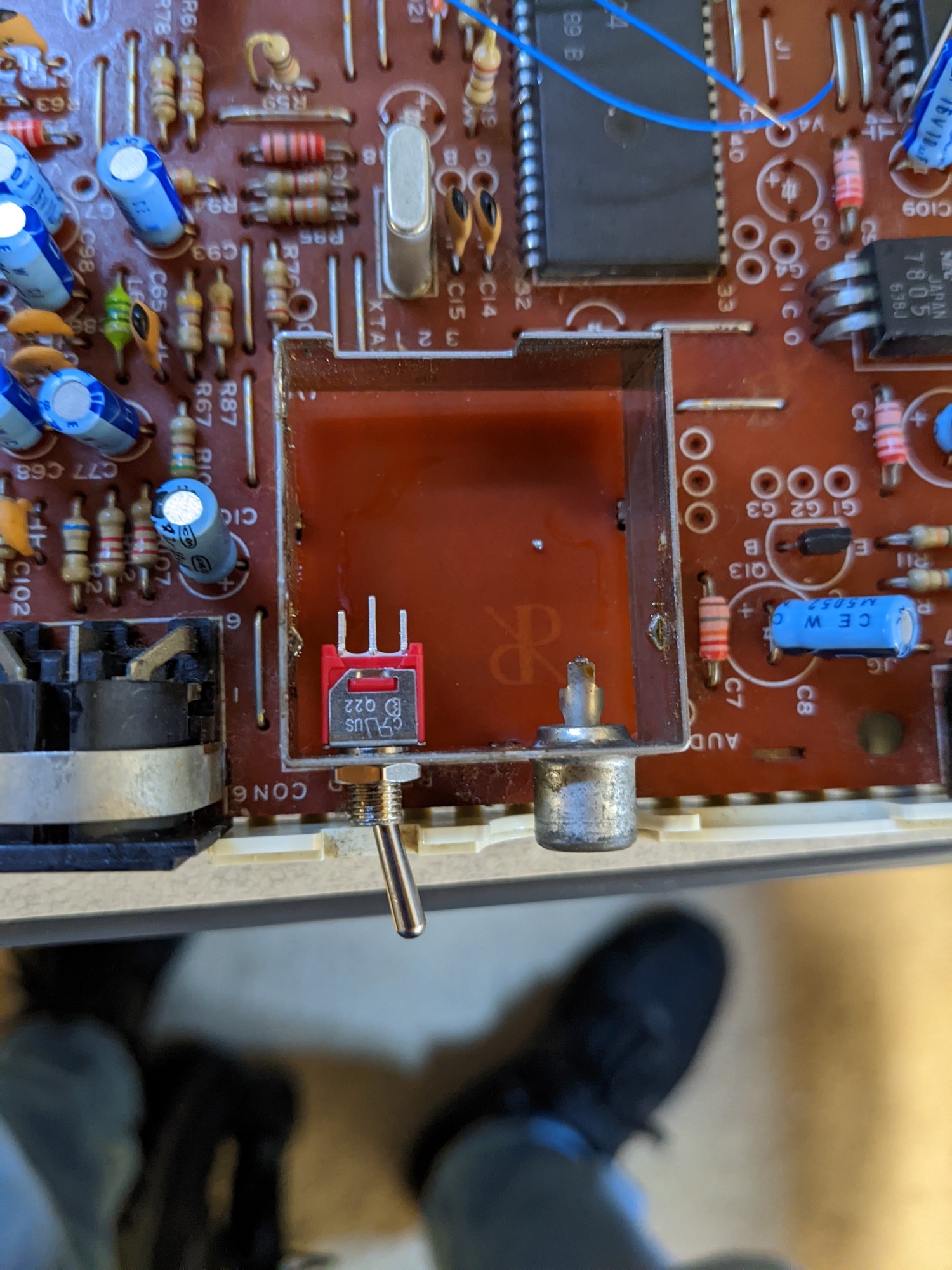
Ok, so maybe this makes me a bad retro citizen, as I totally removed the RF internals. In my defense, it’s RF. Also, it looks clean as hell. Anyways, if someone wanted to, they could totally rebuild the RF circuit. It’d be a lot easier than remaking any cut plastic, that’s for sure.
Wiring Diagram
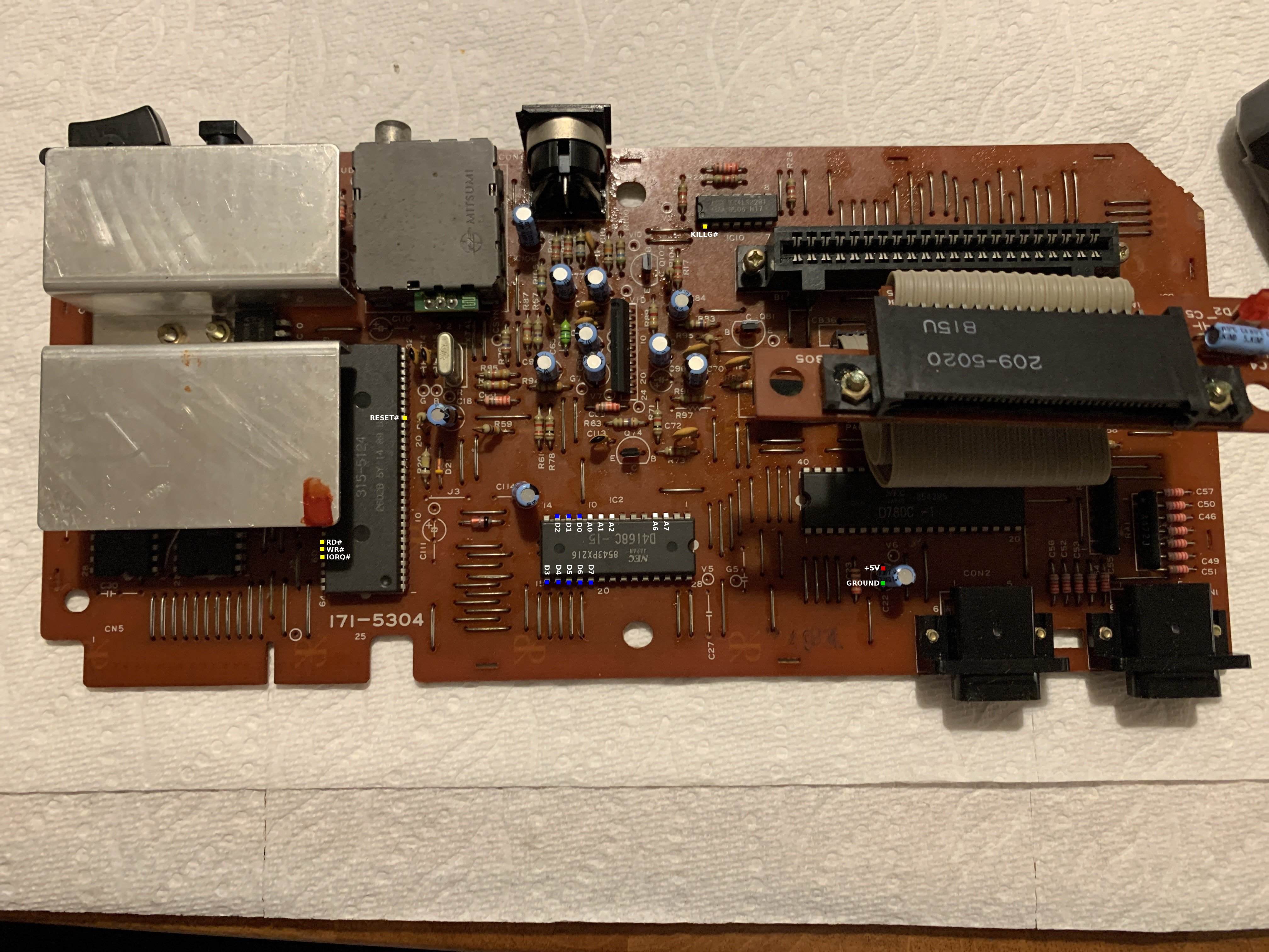
As mentioned before, there was really no good way to avoid a big ol’ rats nest of wires, as all the signals that needed tapping weren’t available at any one place. Most of the signals are available at the expansion bus, but there’s a few extra address lines that are elsewhere. Besides, the signals are all on the bottom of the motherboard, and I really wasn’t that interested in soldering directly to the expansion bus, making it unavailable for future uses (whatever those are…). I color-coded my wiring into a few categories: address lines (white), data lines (blue), control lines (yellow), power (red), and ground (green). The address and data lines all tap IC2, the work RAM. The control lines are almost entirely coming from the IC3, the Video Display Processor (VDP). The power and ground come from a decoupling cap at C22, and lastly, that darn KILLG# (or JyDs) signal, coming from IC10.
| Signal | SMSFM | IC2 (RAM) | IC3 (VDP) | IC10 (OR Gate) | C22 |
|---|---|---|---|---|---|
| WR# | 2 | 59 | |||
| RD# | 4 | 58 | |||
| D7 | 14 | 19 | |||
| D6 | 15 | 18 | |||
| D5 | 16 | 17 | |||
| D4 | 17 | 16 | |||
| D3 | 18 | 15 | |||
| GND | 20 | - | |||
| D2 | 22 | 13 | |||
| D1 | 23 | 12 | |||
| D0 | 24 | 11 | |||
| A0 | 25 | 10 | |||
| A1 | 26 | 9 | |||
| A2 | 27 | 8 | |||
| A6 | 31 | 4 | |||
| A7 | 32 | 3 | |||
| +5V | 35 | + | |||
| IORQ# | 38 | 60 | |||
| KILLG# | 43 | 1 | |||
| RESET# | 46 | 23 |
SMSFM Results
Now that everything is in place, let’s see how it works.
Double Dragon
I had no games prepped on the Master Everdrive to actually test the YM2413’s FM audio. I settled on Double Dragon being the first test, as it was easy to come by.
We have success! It was really weird to hear Double Dragon sound effects rendered in FM as well, but that’s how things are in Master System land. When you opt into FM Unit, you’re forgoing PSG sound, as the original FM Unit was designed for one or the other, not mixing PSG and FM audio together.
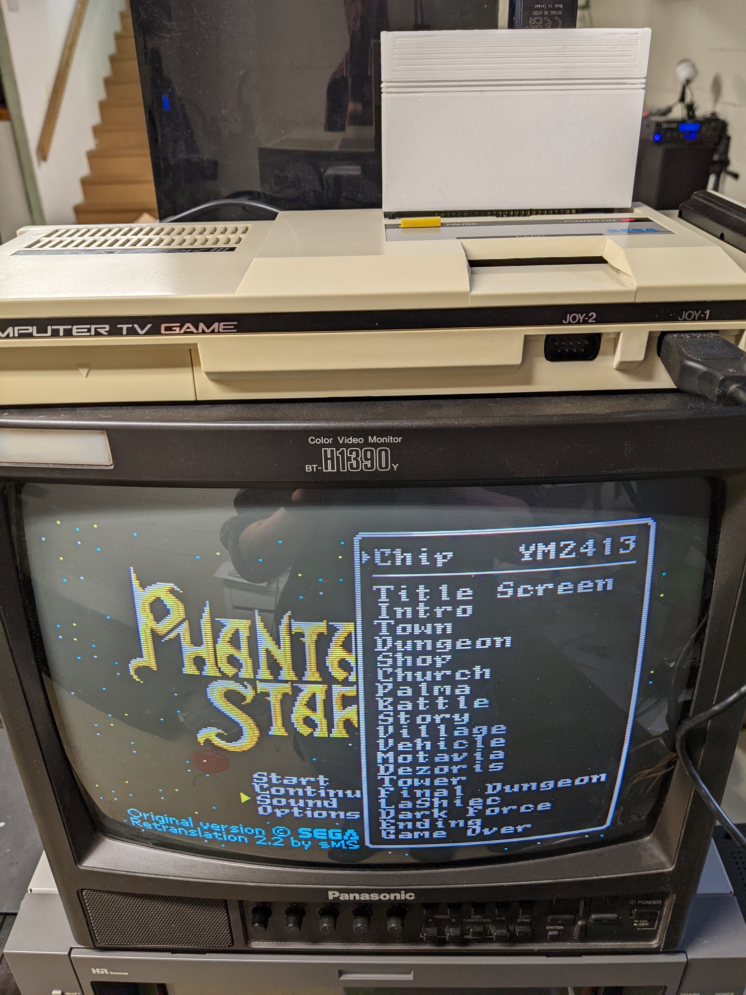
Phantasy Star
For my second test, I was told that Phantasy Star’s fan translation allows you to select PSG or FM audio in the sound test, so that seemed like a very good test. And indeed, I could select between the two chips. In all honesty, I think I prefer the PSG soundtrack over the FM one in this case. Something about the FM sound seems watered down to me, or maybe it’s just still off-putting hearing “16-bit” sound alongside “8-bit” graphics. I dunno, maybe I’ll warm up to it.

Sonic 1 FM
One more test, and this one is interesting. As I mentioned above, the original FM Unit can only do PSG or FM sound at once. There is no mixing of the two simultaneously. I initially thought that the SMSFM had the same limitation. However, there was one homebrew game, Sonic FM, that used a feature seemingly only ever demonstrated by the Japanese Master System’s BIOS, which allowed independent enabling of FM and PSG sound, and mixed the two. I was looking over the SMSFM code trying to understand if this feature could be added, and realized it looked to already be supported! I hadn’t seen this mentioned anywhere on the Internet, but maybe I just missed it.
I’ve already shown a picture of Sonic running, and I don’t have a great way to capture, so instead, here’s someone else showing Sonic FM on a flashcart and a Japanese Master System.
Power Switch
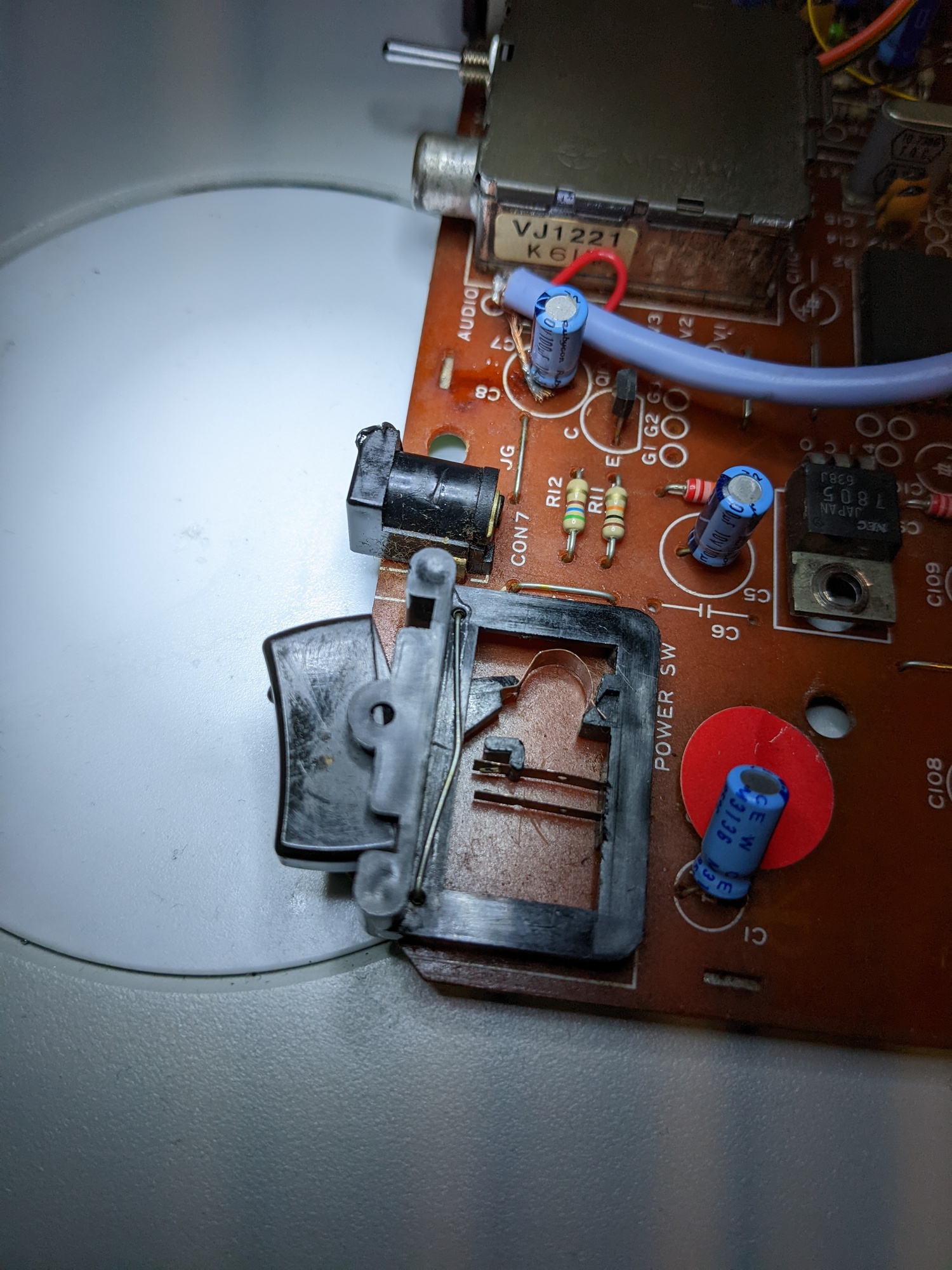
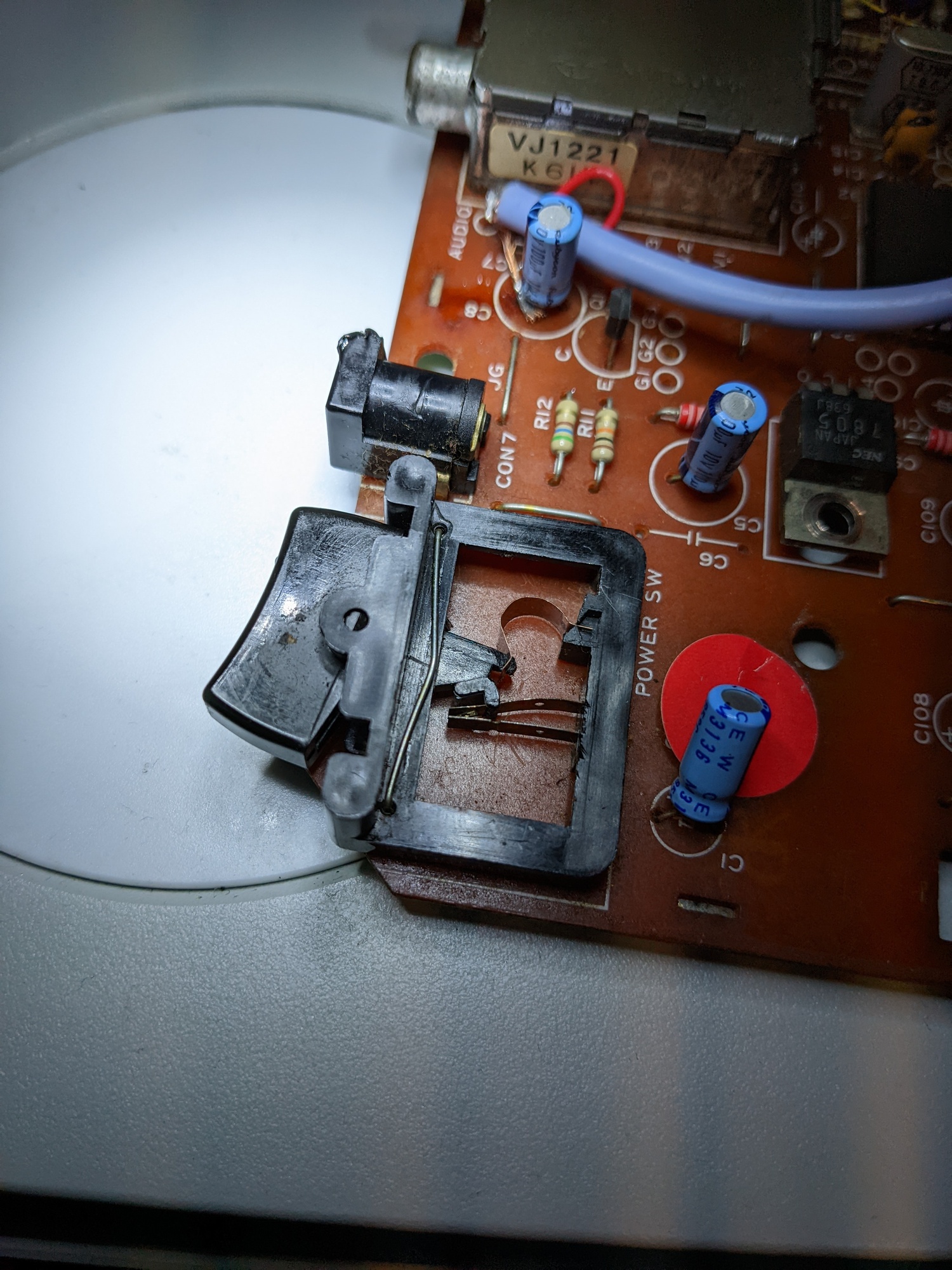
Last, but not least, I came back to check out a problem that I didn’t actually realize was a problem until reading LeadedSolder’s Mark III article. The power switch on my Mark III felt mushy, similar to what he described. It was totally functional, but apparently not snappy like it was supposed to be. At this point, I had everything put back together, so it was somewhat annoying to tear everything back down, especially because I had to remove the huge heatsink on the 5V regulator, which requires access from the bottom of the board, and the bottom case plastic that holds the motherboard in place are not very flexible and it makes me nervous getting the board out. It feels like it’s likely going to snap, but it hasn’t yet, fingers crossed.
Getting the board out, I had to get the bent piece of copper that acts as the spring in the power switch hooked back onto the tilt switch. I was having a hell of a time getting it to go, and I ended up actually taking an Xacto knife to it to whittle down the plastic nub it was supposed to stay on. In the end, the metal “spring” did relent, although I’m not super confident that it’ll stay in place long-term. You might see this re-appear in a future article…
Future Plans and Thanks
In the future, I do want to come back the Mark III and play with some more peripherals. Raphnet has a DIY SMS paddle controller that I’ve been slowly building, so expect to see an article about that whenever it’s done. I also want to try to get the 3D adapter going on the the Mark III. Lastly, I may want to upgrade my Master Everdrive to a newer model that doesn’t do a single flash, which takes time every time I wanna change games. That’s a minor annoyance, but it would also fix my issue with the SD slot being in the wrong spot for Todd’s case.
All in all, this was a very fun project. I really like the look of the Mark III and having all these functional additions and fixes makes it very nice to play on. I’d like to say thanks to both Tianfeng, Retro Frog, and LeadedSolder for their help in this process, as it took me week or so of messing around to get everything working, and it could have been so much more time if I had to start from scratch instead of leaning on the developments and learnings of others.
Thanks for reading!